The Evolution of the FLX Pedal
The pedal software was created using the Buildroot embedded Linux kernel builder combined with the Eclipse IDE
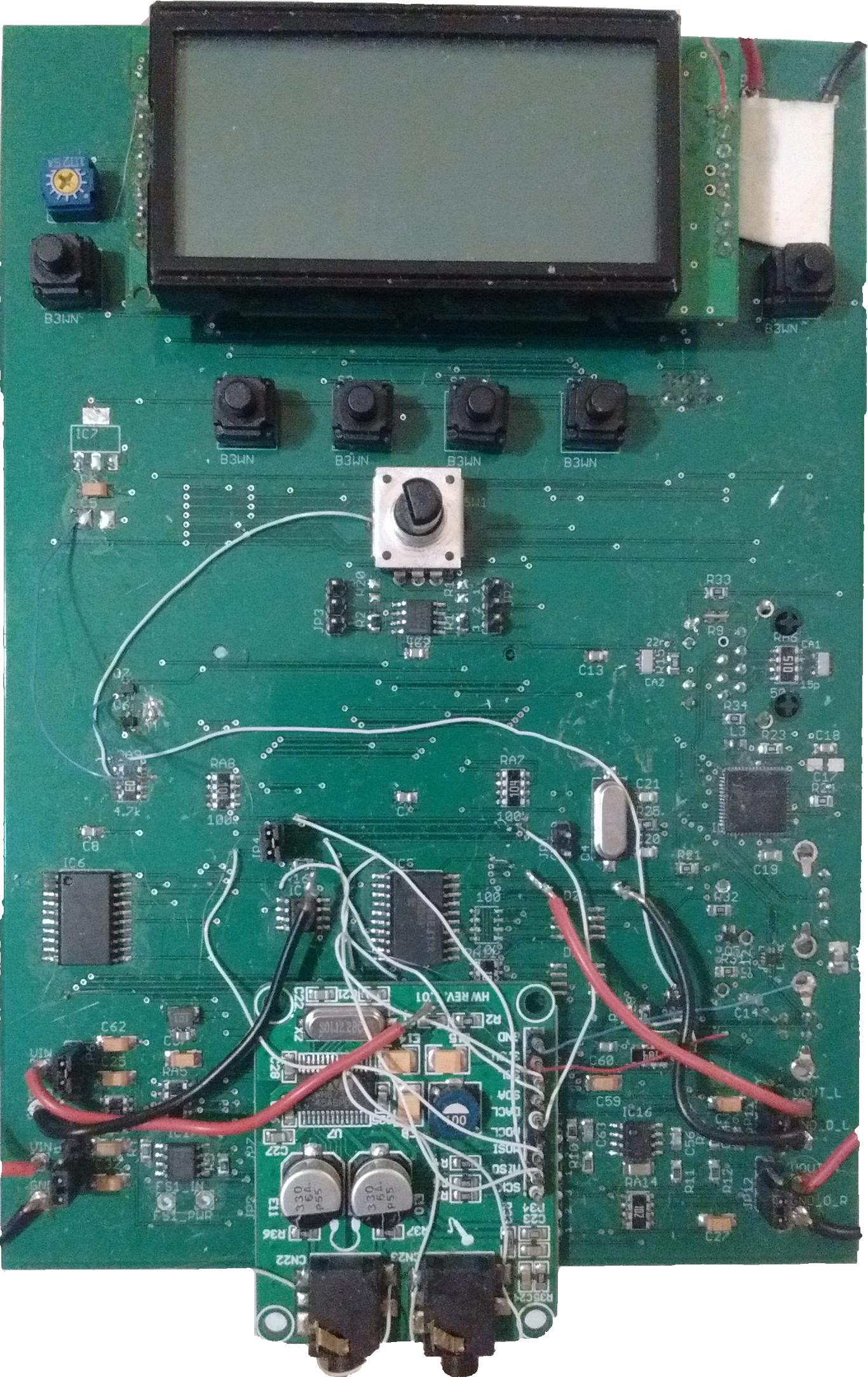
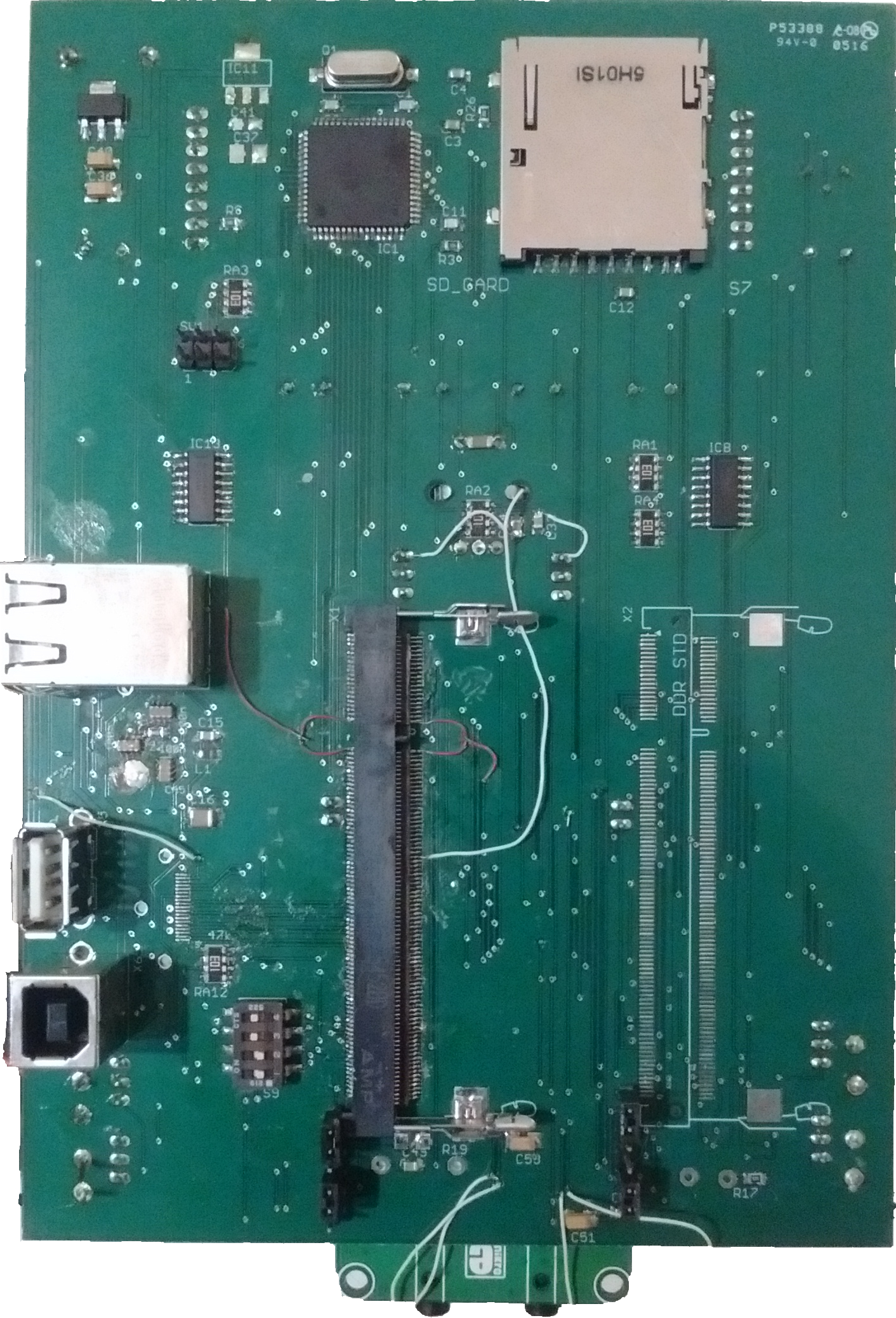
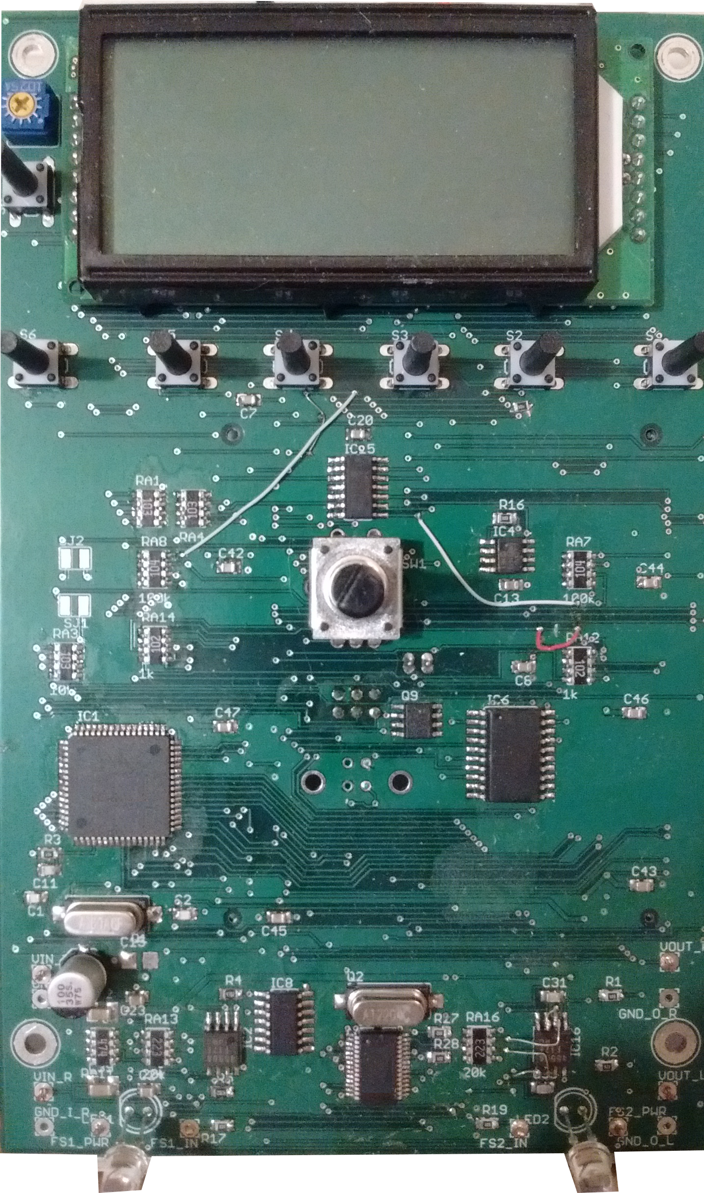
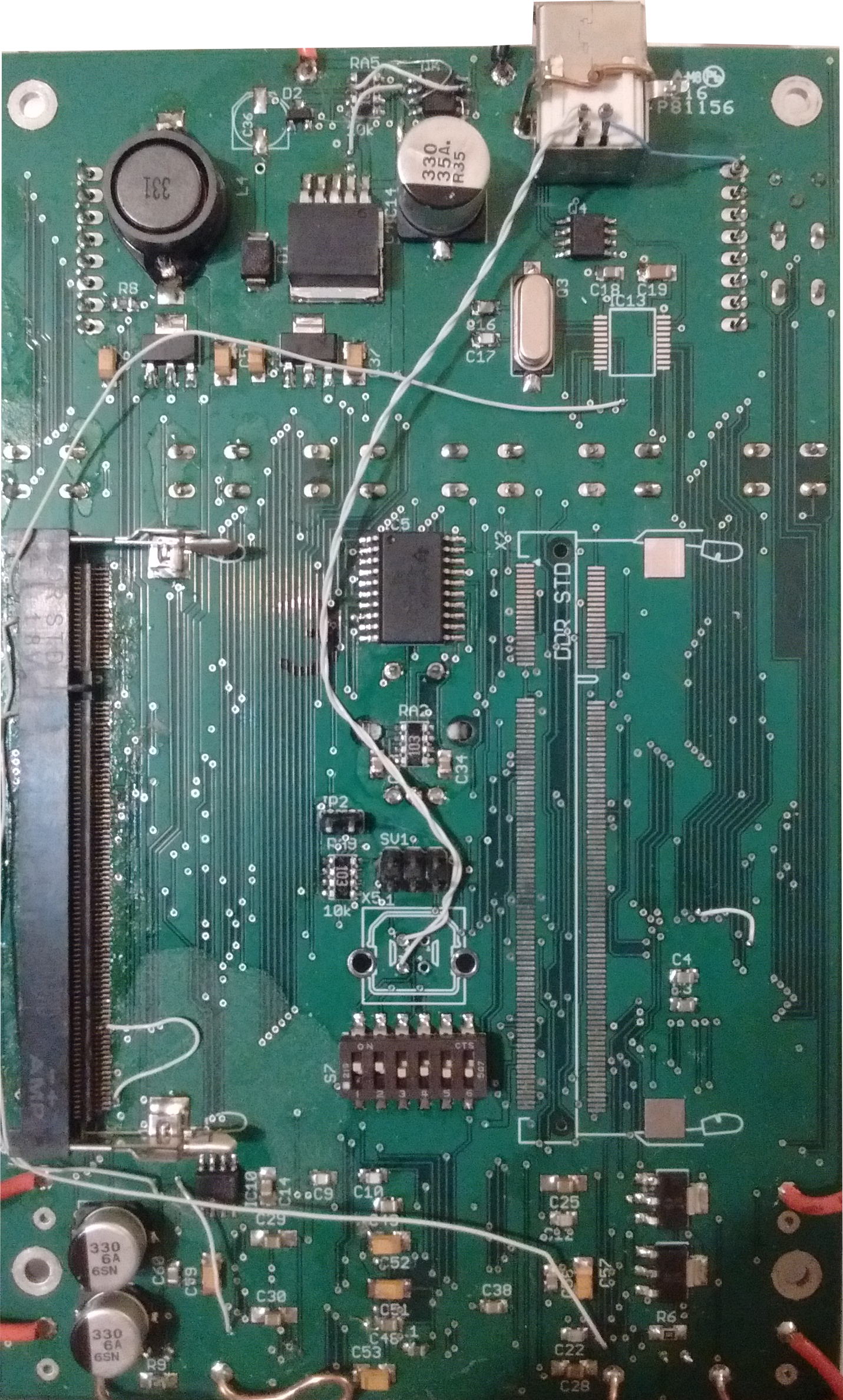
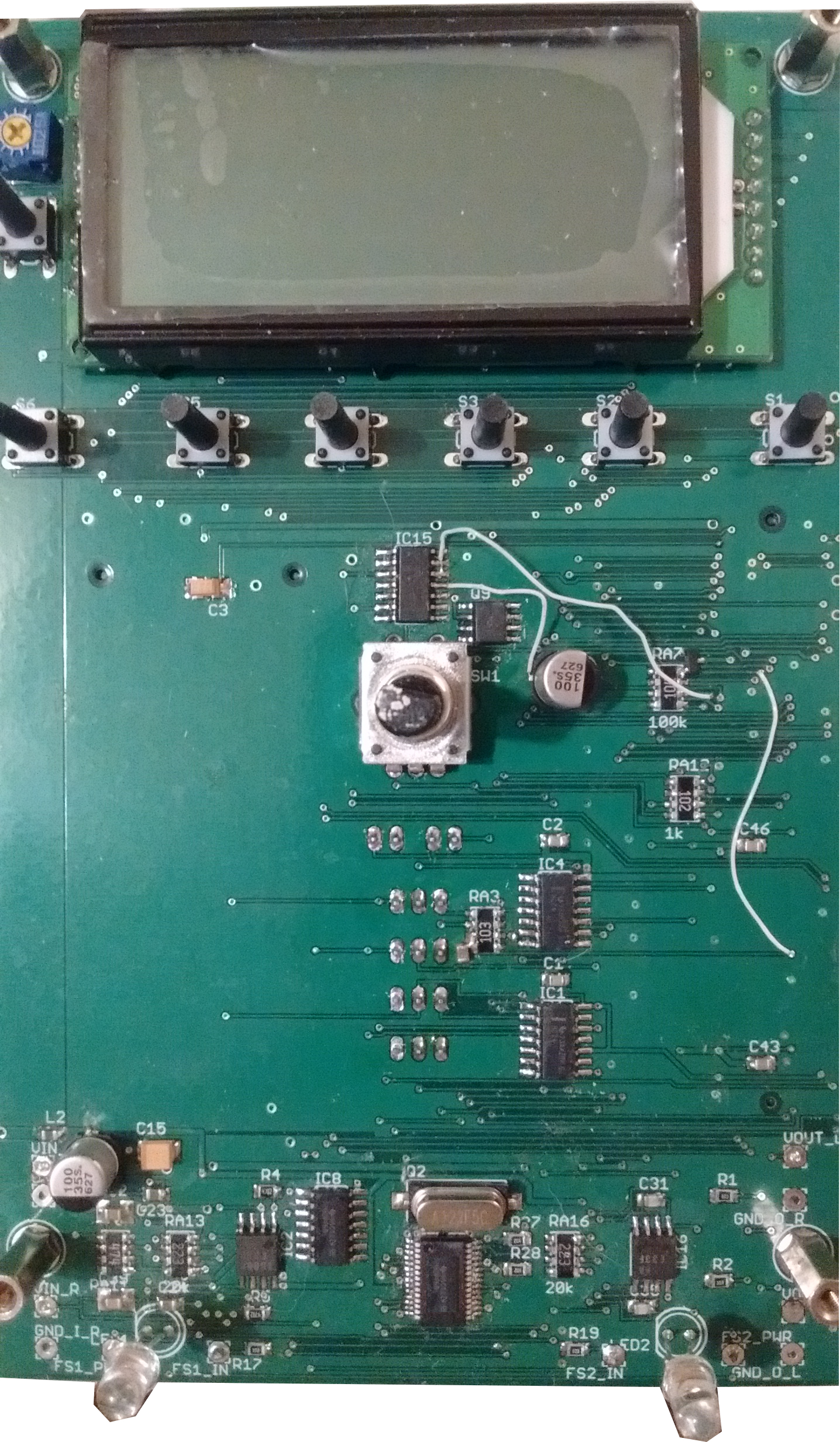
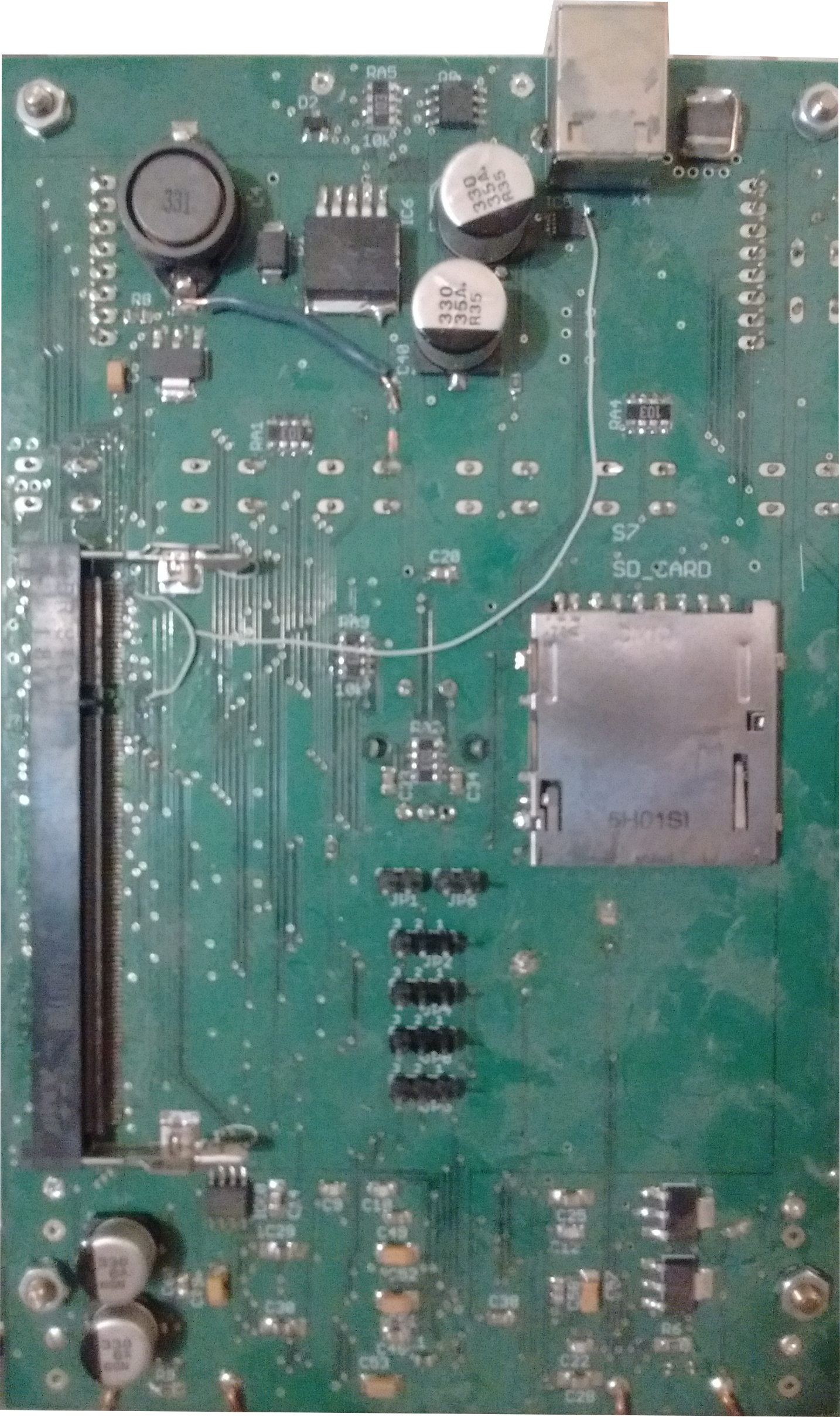
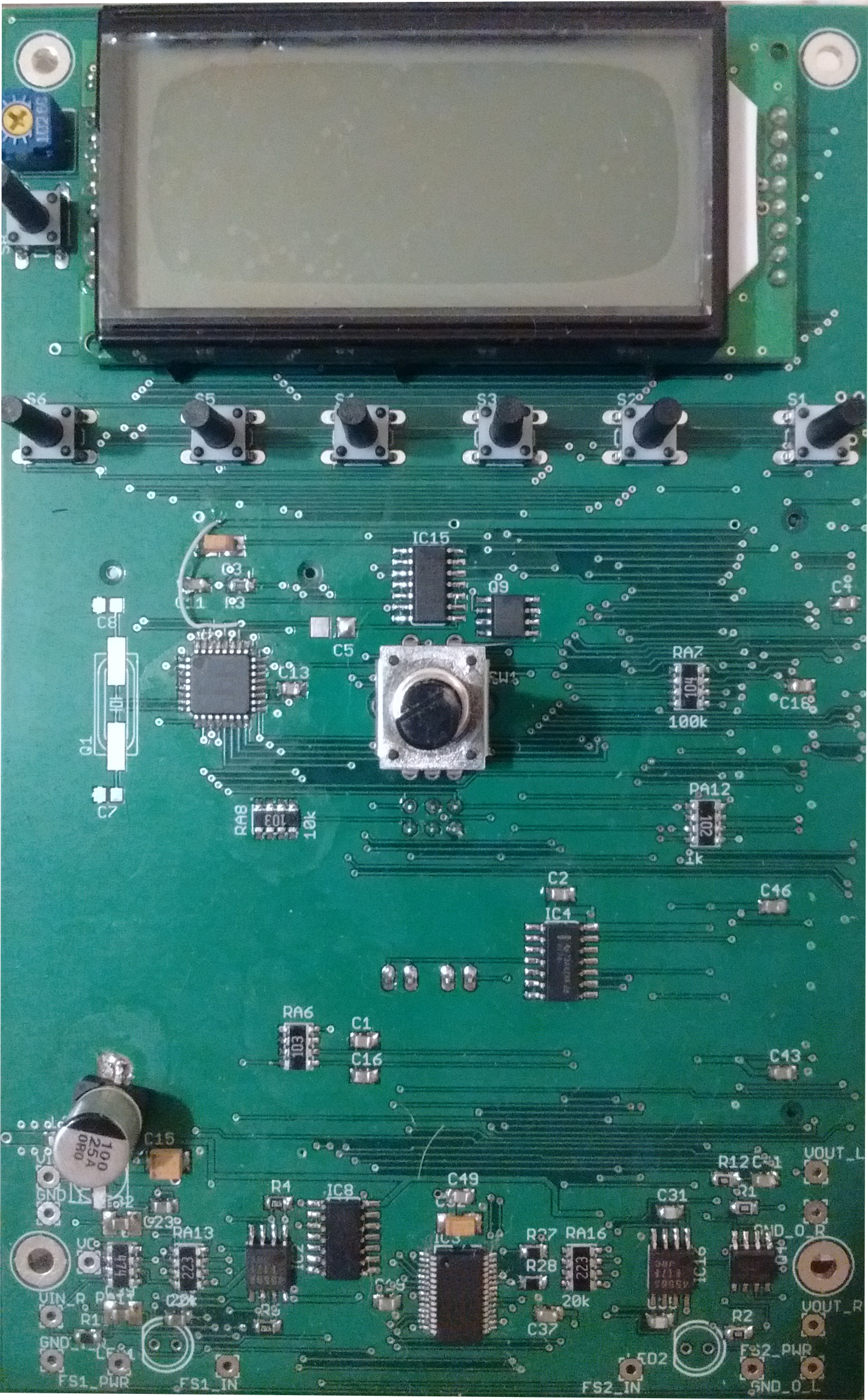
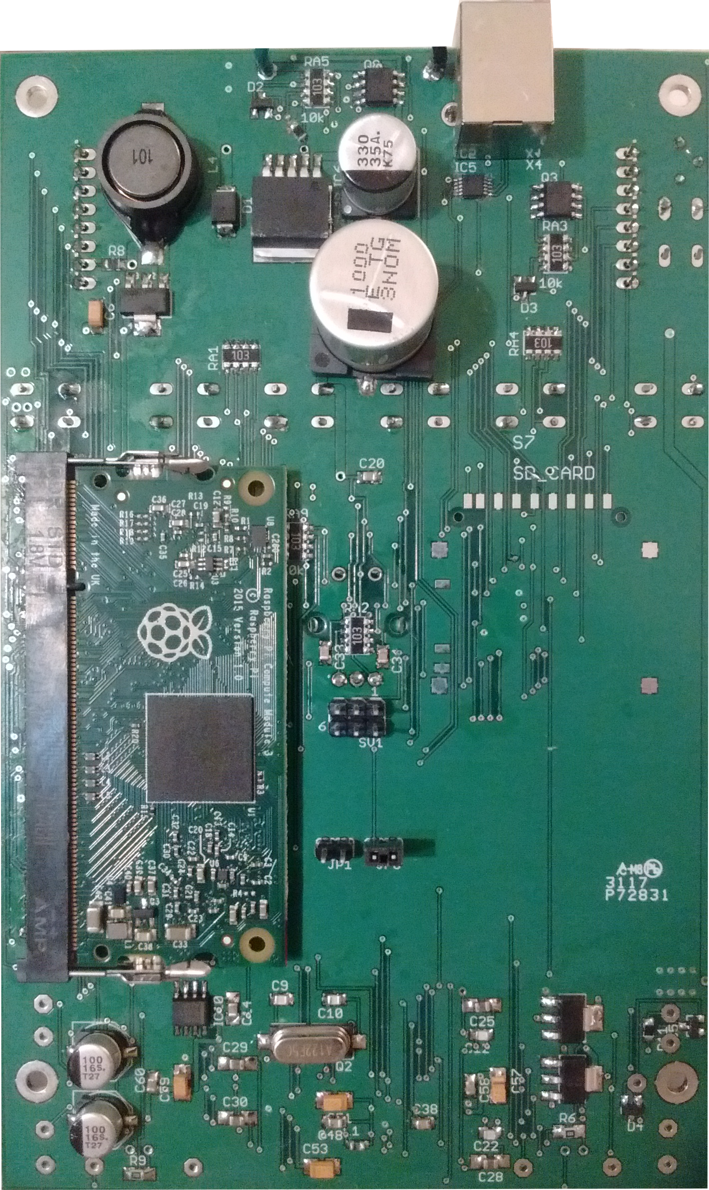
The pedal PCB was created using EAGLE
Version 1
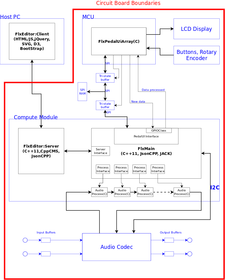
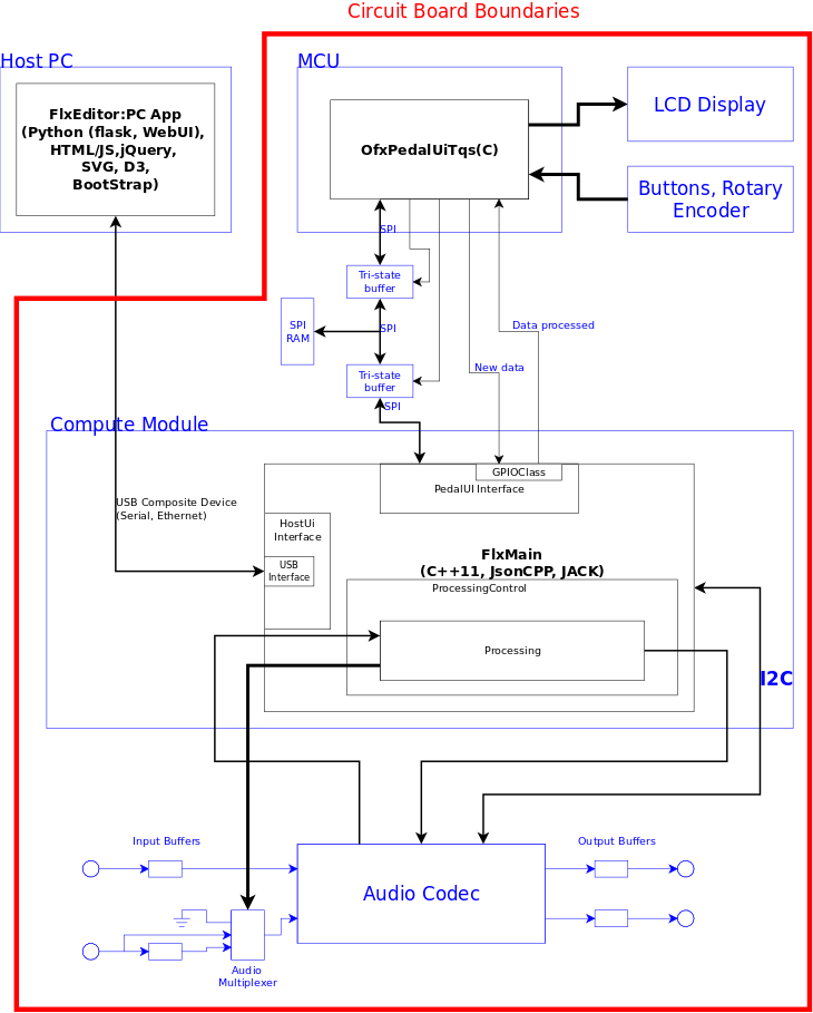
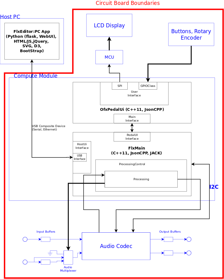
The OfxMain process was launched towards the end of /etc/init.d/rcS. It then launched and handled the OfxEditor embedded server through the ServerInt object. IPC (interprocess communication) between OfxMain and OfxServer was done through request and response FIFOs. Requests from, and responses to, the OfxPedalUiArray, running on the MCU, were sent through the PedalUiInt object.
The MCU interfaced with the Compute Module indirectly via a set of tri-state buffers and an SPI RAM chip. This circuitry arose from the problem of both sides wanting to be masters on the SPI bus (I later realized that the reason the MCU didn't work in the slave configuration was that I was using the wrong syntax for an ISR (Interrupt Service Routine) function in the C code. Much of the initial code for the MCU came from a previous project using a different compiler.) The solution was to use an SPI RAM as intermediary memory storage with each side having its own section of memory for recieving new data. The MCU sent data to the Compute Module by first enabling it's own access to the SPI bus through the tri-state buffer and then writing into the Compute Modules new data sector. The MCU disabled its SPI access, sent a signal to the Compute Module indicating it had new memory, enabled the Compute Module's SPI access, and waited for a response from the Compute Module. The Compute Module processed the data and then signaled the MCU that the response data is in the MCU's memory sector. While this hardware could certainly be eliminated by having a direct SPI connection (and the right ISR syntax), it did provide capability for expanding the number of Compute Modules. While it was never used, the PCB had the solder footprint for another Compute Module for expanding the pedals capability. The Compute Modules could communicate with each other used the SPI RAM setup, with the MCU acting as a data router.
OfxMain created and initialized ProcessInt objects from the combo files stored in the pedal at /home/Combos. Each object launched and handled a specific audio process (determined by the combo data) that interconnected with the other processes handled by other ProcessInt objects to create a combo. IPC between the ProcessInt objects and the audio processes were done using shared mapped memory. The audio processes were interconnected and disconnected by the ConnectionCont class (not shown), which used the JACK connect and disconnect commands.
The OfxEditor served the client browser with the editor application. This was a quasi-MVC application, where the model is the OfxMain process. The graphics were done using SVG (Scalable Vector Graphics) and D3, a javascript library for using SVG that could be described as jQuery for SVG. This was a primative version of the editor, as the process symbols were rough and no process parameter controllers were present (more about those in the next Version).
This version of the FLX Pedal software worked well enough from a technical perspective. However, it took up to 12 seconds to change between combos. For a guitarist playing a live gig, this was a non-starter.
Audio Processes
3BFilter: Splits a signal into a low band, mid band, and high band.
- Parameters
- Low-to-mid frequency cutoff: Sets the low band's lowpass frequency and the mid band's highpass frequency.
- Mid-to-high frequency cutoff: Sets the mid band's lowpass frequency and the high band's highpass frequency.
- Roll-off frequency: Sets the high band's lowpass frequency.
Delay: Used for creating delay based effects.
- Parameters
- Delay time
LohiFilter: Splits a signal into a low band and high band.
- Parameters
- Low-to-high frequency cutoff
Mixer: Mixes together 3 input signals.
- Parameters
- Input1 Level
- Input2 Level
- Input3 Level
- Output Level
Volume
- Parameters
- Volume
Waveshaper: Used for distortion effects.
- Parameters
- Gain: Sets the waveshapers amplification level.
- Edge: Sets the hardness of the clipping, from soft (vacuum tube) to hard (solid-state).
- Mix: Sets the mix ratio between the clean and distorted signal.
Version 2
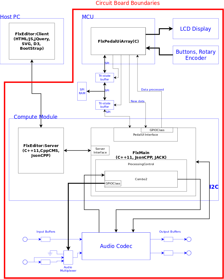
Due to the time needed for switching between combos, the processes and interconnections needed to be integrated into OfxMain. This meant that interconnections done by the JACK server would no longer be available, and another method for interconnecting processes had to be designed. This meant that both the processes and the interconnections had to be sorted by signal flow, and it could not be assumed that either the process list or the interconnection list created from the combo file were in order.
An algorithm, or set of algorithms, had to be designed to sort both lists. In the end, algorithms were devised in the ComboDataInt class that used the unsorted interconnections to sort the processes, and in doing so, also sorted the interconnections, themselves.
One new source file and two new classes were also created: Effects2, Combo2, and ProcessingControl.
Effects2 contained functions of the the signal processes, as well as functions for controlling the process parameters (i.e. envelope generator and low frequency oscillator), and functions for loading the process data. Combo2 class contained data structures for process and control sequences, and process interconnections. It also contained functions for loading, running and stopping the processes in a combo, as well as functions for updating parameter data in the processes and controls. The ProcessingControl class contained the combo class, and functions for loading, starting, and stopping the combos, in addition to updating combo parameter data.
The OfxEditor for this version was a more refined version of the previous editor. It contained the finished process symbols as well as symbols for the process parameter controls.
Version 3
A patent search revealed that an embedded editor like OfxEditor had already been patented by a large company. To avoid re-writing all the editor code, the client-side code was turned into a PC application using python flask and WebUI modules, and a USB interface. In OfxMain, the ServerInt class was replaced by a HostUi class contained a UsbInt object.
Firmware architecture was changed to quasi task queue scheduling. The task queue and functions for the queue are in the code ... unfortunately I forgot to put in code that uses them, hence the “quasi” <facepalm>. As it stood, “task” and “nextTask” variables were used.
Version 4
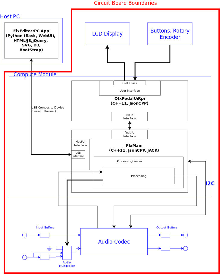
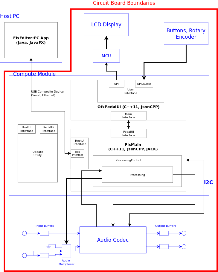
As a cost-cutting measure, all functionality that was in the MCU OfxPedalUi was put into a new linux process called OfxPedalUiRpi. The OfxPedalUiRpi process interfaced with OfxMain through request and response FIFOs, directly wrote to the LCD display and read the buttons, and indirectly read the rotary encoder through logic circuits. While this worked as expected, the larger combos caused a slower response in the pedal user interface. In addition to the slower response, until the OfxPedalUi was launched by OfxMain, the LCD display was blank.
Version 5
As as result of the increased user interface response time with larger combos, the function of writing to the LCD was transferred to a small MCU. OfxPedalUi came back as a linux process. However, in this case, the process read from the buttons and rotary encoder throught the GPIO class the while it used an SpiInt object to write to the MCU driving the LCD. In addition to driving the LCD, the smaller MCU also controlled the pedal power on/off and LCD display during those periods.
Version 6
An independent process call UpdateUtility was added for updating the FlxPedal software. UpdateUtility was made an independent process to avoid potentially bricking the pedal from a bad update.
At this point, FlxEditor was re-written in Java using JavaFX.
Click here for the current FlxMain code.
Click here for the current FlxPedalUi code.
Click here for the UpdateUtility code.